Post-Processing Kinematic (PPK)
How PPK works
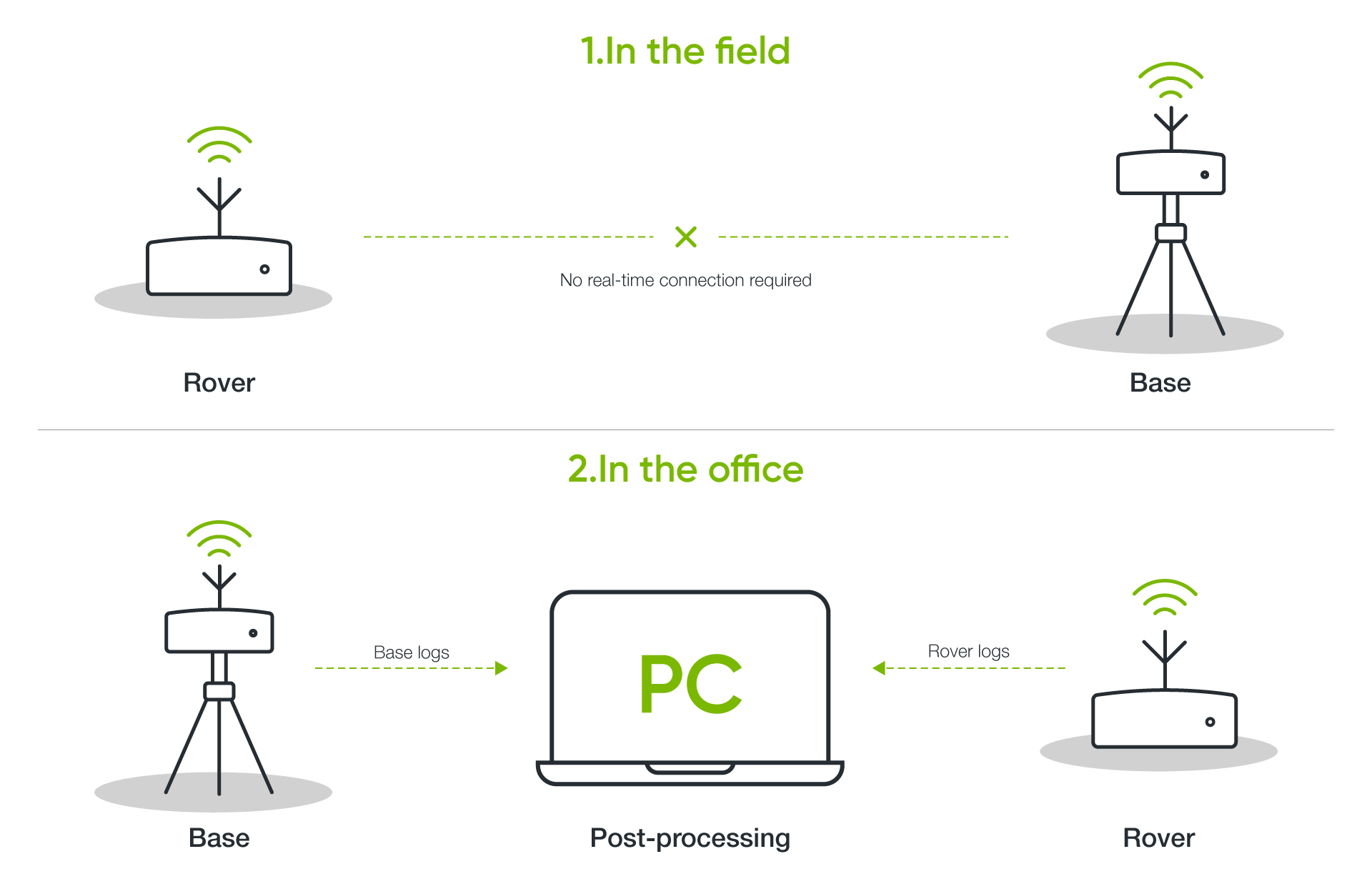
Both the stationary base station and the rover record raw GNSS satellite observational data independently onto local storage cards during operation. After the mission is complete, specialized software merges and cross-references both datasets to resolve positional corrections after the fact.
When to choose PPK
PPK is used when operating in remote areas with poor radio/cellular coverage, when flying long distances or around dense vegetation where signals frequently break or to prioritize maximum data reliability over instant results.
Differences between RTK and PPK
Both RTK (Real-Time Kinematic) and PPK (Post-Processing Kinematic) are differential GNSS correction techniques that deliver centimeter-level positioning accuracy. The fundamental difference lies in when and how the correction data is applied to the raw positioning signals.
| Feature | RTK (Real-Time Kinematic) | PPK (Post-Processing Kinematic) |
|---|---|---|
| Data Processing | In real time, directly during flight or survey | After data collection, during post-processing software workflow |
| Communication Link | Requires an active radio or cellular (NTRIP) data link | No live data link required |
| Signal Dependency | Highly vulnerable to signal dropouts, terrain obstructions, and range limits | Immune to real-time telemetry signal losses |
| Accuracy Level | Centimeter-level, provided the link remains stable | Centimeter-level, often more consistent across wide areas |
| Field Workflow | Immediate feedback; requires setting up base links on-site | Simple in-field capture; requires extra time for processing later |
| Best Use Cases | Live navigation, precise landing, immediate boundary stakeouts | Mapping large rural areas, dense forests, or long corridor surveys |
Emlid Reach M2 setup
Power
You can power Reach M2 from SkyHub USB port providing 5 Volts over USB to Micro USB cable or over USB to JST-GH cable. No other connection between Reach M2 and SkyHub is needed as SkyHub acts only as a power supply for Reach M2 in this scenario.
Caution
Do not plug two power supplies at the same time as it may damage the device.
Antenna placement on UAV
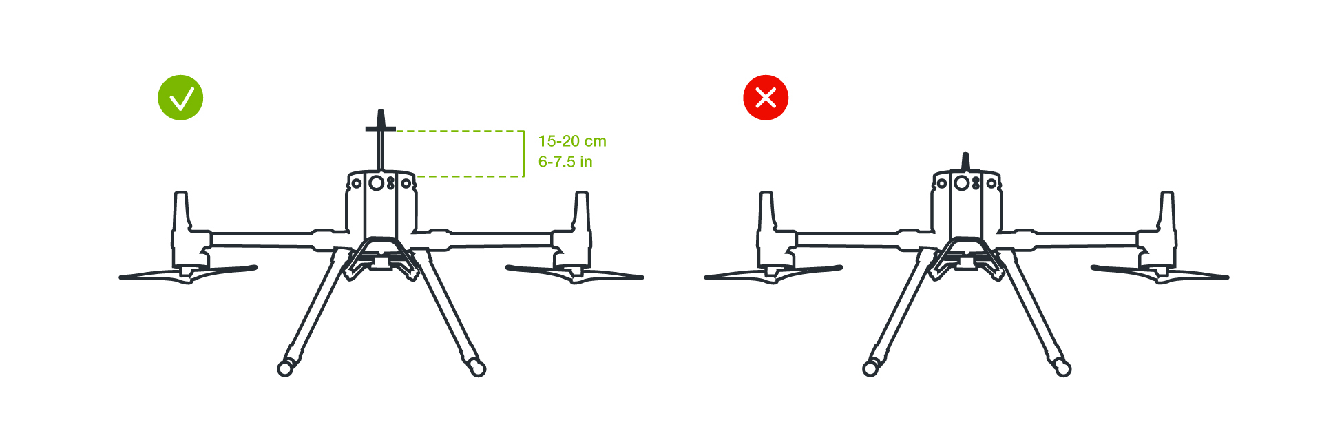
The antenna needs to have a clear sky view 30 degrees above the horizon. There should be no obstacles that could block the view like buildings, trees, cars, humans, laptops, etc.
Info
Important: Place the antenna on top of the UAV.
How to log data for PPK UAV mapping
With PPK workflow accurate positioning does not happen in real time, all algorithms are applied afterwards. Both base on the ground and rover on a UAV record raw GNSS logs which will be further used for post-processing of the data set, geotagging of the resulting photos and mapping in the photogrammetric software.
Logging on the rover
- Make sure your mobile device or computer are in same WiFi network with Reach M2 “Emlid Flow” application on mobile device or access Reach M2 via internet browser on your computer.
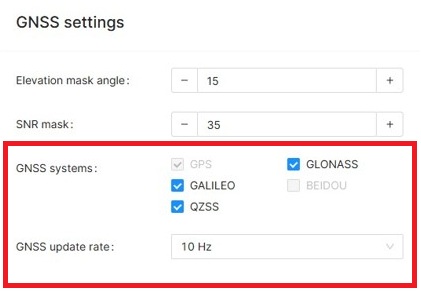
- In “GNSS Settings” section set the satellite systems and update rate at 10 Hz.
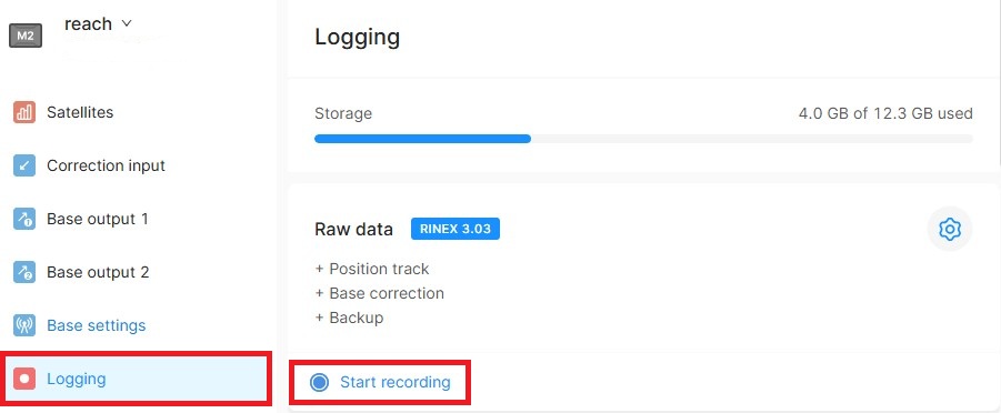
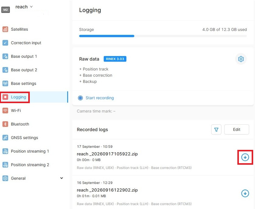
- In “Logging” section enable log recording by using the “Start recording” button.
Download logs from rover
Caution
Wait for data processing to finish after stopping the recording and before attempting download.
- Connect to rover
- Go to the "Recorded logs" section at the bottom of the "Logging" screen.
- Look up your file in the list export the file using the “Download” button.
- Save the log on your device for later processing.
Download logs from base
- Connect to base station
- Go to the "Recorded logs" section at the bottom of the "Logging" screen.
- Look up your file in the list and export the file using the “Download” button.
- Save the log on your device for later processing.
Info
Important: Ensure that log files are collected in SAME time on both rover and base otherwise PPK data processing will not be possible.
Tip
You can use base logs from your own base device or you can download logs from NTRIP provider. Make sure you use logs from closest NTRIP base relative to your survey area.
Post processing using Emlid Studio software
- Open “Emlid studio” software on your computer.
- Import log from rover into field "Rover"
- Import log from base into field "Base"
- Import log from rover into filed "Navigation"
- Click “Process”
- Once processing is done, click "Show result files". Generated .pos file will hold processed data with much greater precision.
Example of contents of generated .pos file after post-processing using Emlid Studio post processing software.
Header Information:
program: Software version used.
input files: RINEX observation files from rover and base.
obs start: Observation start, GPST.
obs end: Observation end, GPST.
ref pos: Base reference position Latitude, Longitude, Height.
Data Columns Breakdown:
| Column Header | Field Name | Description & Units |
|---|---|---|
| GPST | GPS Time | Timestamp of the position fix in GPS Time (YYYY/MM/DD hh:mm:ss.sss). |
| latitude(deg) | Latitude | Estimated rover latitude in decimal degrees (WGS84). |
| longitude(deg) | Longitude | Estimated rover longitude in decimal degrees (WGS84). |
| height(m) | Height | Ellipsoidal height above the WGS84 ellipsoid in meters. |
| Q | Solution Quality | 1: Fix (RTK Fixed solution) 2: Float (RTK Float solution) 3: SBAS 4: DGPS 5: Single 6: PPP |
| ns | Number of Satellites | Number of valid satellites used in the positioning solution. |
| sdn(m) | Standard Deviation North | Estimated position error (standard deviation) in the North direction in meters. |
| sde(m) | Standard Deviation East | Estimated position error (standard deviation) in the East direction in meters. |
| sdu(m) | Standard Deviation Up | Estimated position error (standard deviation) in the Up (Vertical) direction in meters. |
| sdne(m) | Covariance North-East | Estimated error covariance between North and East components in meters. |
| sdeu(m) | Covariance East-Up | Estimated error covariance between East and Up components in meters. |
| sdun(m) | Covariance Up-North | Estimated error covariance between Up and North components in meters. |
| age(s) | Age of Differential | Delay/age of the base station correction data in seconds. |
| ratio | Ambiguity Validation Ratio | AR ratio factor used for integer ambiguity resolution validation (higher values indicate greater confidence in a Fixed solution). |
