SBES: EchoLogger
Caution
The sensor may be connected/disconnected only when the system is powered off.
- Attach the Universal Heavy Payload mount to the bottom of your drone.
- Attach the Echologger to the Universal Heavy Payload mount.
- Connect the cable to the SkyHub Connector #4 (white).
Power on the system.
- Establish either the drone link or auxiliary connection with the SkyHub in the UgCS-CPM software.
- On the main screen of the UgCS-CPM, click on the “Payloads” button.
- From the available payload list, enable the “SBES: EchoLogger”.
- Press the “Save” button and confirm system reload.
Wait until the reload process is finished and the connection to the SkyHub is reestablished.
- On the main screen of the UgCS-CPM, click the “Start” button.
- From the drop-down widget list, select the “SBES: EchoLogger single-frequency” if you have the ECT400 model, or “SBES: EchoLogger dual-frequency” if you have the D052S/D24S model, and press the blue “plus” button.
- To access the configuration menu, press on the “three-dot” icon on the upper right corner of the widget and select “Settings”.
SBES: EchoLogger Configuration Parameters (Single frequency)
| Parameter | Default | Min | Max | Precision | Unit | Options | Description |
|---|---|---|---|---|---|---|---|
| Min depth | 0.5 | 0.0 | 200.0 | 0.01 | m | Higher value from sensor will appear red | |
| Max depth | 20.0 | 0.0 | 200.0 | 0.01 | m | Lower value from sensor will appear red | |
| Range | 10 | m | 2, 3, 5, 10, 15, 20, 30, 40, 50, 60, 70, 80, 90, 100, 120, 150, 200 | Maximum measurement range for high frequency | |||
| Measurement interval | 0.1 | 0.0 | 4.0 | 0.1 | s | Measurement interval | |
| Output data mode | NMEA | NMEA, ECHOSOUNDER | NMEA: Output data in NMEA format only ECHOSOUNDER: Output data in NMEA and SEG-Y formats | ||||
| Sampling rate | 0 | Hz | 0, 6250, 12500, 25000, 50000, 100000 | Sensor internal sampling frequency, relevant only for ECHOSOUNDER mode | |||
| Gain | 0 | dB | +50, +40, +30, +20, +10, +6, 0, -6, -10, -20, -30, -40, -50 | Signal gain, dB | |||
| Cable length | 2.28 | 0.0 | 10.0 | 0.01 | m | Distance from altimeter to bottom of echosounder | |
| Altimeter threshold | 10 | 5, 10, 15, 20, 30, 40, 50, 60, 70 | Altimeter threshold in percents of a full scale | ||||
| Transmitted pulse length | 50 | 10 | 200 | 10 | us | Transmission pulse length, microsecond | |
| Dead zone | 500 | 0 | 10000 | 1 | mm | Near field zone where detection is ignored, mm | |
| Data log dir | /data/skyhub_logs | Path on SkyHub storage where data is saved | |||||
| Max sensor angle | 20 | 0 | 90 | 1 | degree | The data are not recorded if the sensor tilt/roll value is greater than the specified value, degree | |
| Sensor depth | 0.1 | 0.0 | 1.0 | 0.1 | m | Minimum sensor depth below water surface to record data in NMEA and SGY | |
| Payload Id | 216 | 192 | 220 | 1 | Payload Id | ||
| Raw log | False | Write raw data byte stream into separate log | |||||
| Raw log path | /data/skyhub_logs | Path to SkyHub storage for raw log files | |||||
| Altitude source | Default | Lightware SF30D, Ainstein US-D1, Nanoradar NRA24, Mavlink (autopilot), Default | Altimeter that will be used for altitude data | ||||
| UART baud rate | 115200 | bps | 4800, 9600, 19200, 38400, 57600, 115200, 230400, 460800, 921600 | Connection port baud rate, 115200 recommended by manufacturer | |||
| Serial device | Connector #4 | Connector #4, Connector #5 | SkyHub connector number where altimeter is connected |
SBES: EchoLogger Configuration Parameters (Dual frequency)
| Parameter | Default | Min | Max | Precision | Unit | Options | Description |
|---|---|---|---|---|---|---|---|
| Min depth | 0.5 | 0.0 | 200.0 | 0.01 | m | Higher value from sensor will appear red | |
| Max depth | 20.0 | 0.0 | 200.0 | 0.01 | m | Lower value from sensor will appear red | |
| Range high | 10 | m | 2, 3, 5, 10, 15, 20, 30, 40, 50, 60, 70, 80, 90, 100, 120, 150, 200 | Maximum measurement range for high frequency | |||
| Range low | 10 | m | 2, 3, 5, 10, 15, 20, 30, 40, 50, 60, 70, 80, 90, 100, 120, 150, 200 | Maximum measurement range for low frequency | |||
| Measurement interval | 0.1 | 0.0 | 4.0 | 0.1 | s | Measurement interval | |
| Output data mode | NMEA | NMEA, ECHOSOUNDER | NMEA: Output data in NMEA format only ECHOSOUNDER: Output data in NMEA and SEG-Y formats | ||||
| Sampling rate | 0 | Hz | 0, 6250, 12500, 25000, 50000, 100000 | Sensor internal sampling frequency, relevant only for ECHOSOUNDER mode | |||
| Gain high | 0 | dB | +50, +40, +30, +20, +10, +6, 0, -6, -10, -20, -30, -40, -50 | Signal gain for high frequency channel, dB | |||
| Gain low | 0 | dB | +50, +40, +30, +20, +10, +6, 0, -6, -10, -20, -30, -40, -50 | Signal gain for low frequency channel, dB | |||
| Cable length | 2.28 | 0.0 | 10.0 | 0.01 | m | Distance from altimeter to bottom of echosounder | |
| Altimeter threshold high | 10 | 5, 10, 15, 20, 30, 40, 50, 60, 70 | Altimeter threshold in percents of a full scale for high frequency | ||||
| Altimeter threshold low | 10 | 5, 10, 15, 20, 30, 40, 50, 60, 70 | Altimeter threshold in percents of a full scale for low frequency | ||||
| Transmitted pulse length high | 50 | 10 | 200 | 1 | us | Transmission pulse length for high frequency channel, microsecond | |
| Transmitted pulse length low | 50 | 10 | 200 | 1 | us | Transmission pulse length for low frequency channel, microsecond | |
| Dead zone, high | 300 | 150 | 10000 | 1 | mm | Near field zone where detection is ignored for high acoustic frequency, mm | |
| Dead zone, low | 1000 | 500 | 10000 | 1 | mm | Near field zone where detection is ignored for low acoustic frequency, mm | |
| Data log dir | /data/skyhub_logs | Path on SkyHub storage where data is saved | |||||
| Max sensor angle | 20 | 0 | 90 | 1 | degree | The data are not recorded if the sensor tilt/roll value is greater than the specified value, degree | |
| Sensor depth | 0.1 | 0.0 | 1.0 | 0.1 | m | Minimum sensor depth below water surface to record data in NMEA and SGY | |
| Payload Id | 216 | 192 | 220 | 1 | Payload Id | ||
| Raw log | False | Write raw data byte stream into separate log | |||||
| Raw log path | /data/skyhub_logs | Path to SkyHub storage for raw log files | |||||
| Altitude source | Default | Lightware SF30D, Ainstein US-D1, Nanoradar NRA24, Mavlink (autopilot), Default | Altimeter that will be used for altitude data | ||||
| UART baud rate | 115200 | bps | 4800, 9600, 19200, 38400, 57600, 115200, 230400, 460800, 921600 | Connection port baud rate, 115200 recommended by manufacturer | |||
| Serial device | Connector #4 | Connector #4, Connector #5 | SkyHub connector number where altimeter is connected |
Configuring Parameters according to Survey Depth Range
As you prepare for your bathymetry mission, an important piece of information to have beforehand, at least roughly, is the maximum expected depth of the water body you plan to survey. For that, you can use historical data or a best estimate. A few parameters must then be set on your echosounder which depend on that. See the tables below and guide yourself by your survey's depth range.
Range x Measurement interval for EchoLogger ECT400
| Range (m) | Measurement interval for NMEA mode (s) | Measurement interval for Echosounder mode (s) |
|---|---|---|
| 2 | 0.1 | 0.25 |
| 10 | 0.1 | 0.5 |
| 20 | 0.2 | 1 |
| 40 | 0.2 | 2 |
| 80 | 0.25 | 2 |
| 100 | 0.33 | 2.5 |
Range x Measurement interval for EchoLogger ECT D24s and ECT D052/D032
| Range (m) | Measurement interval for NMEA mode (s) | Measurement interval for Echosounder mode (s) |
|---|---|---|
| 1 | 0.1 | 0.25 |
| 2 | 0.1 | 0.33 |
| 5 | 0.1 | 0.5 |
| 10 | 0.1 | 1 |
| 20 | 0.125 | 2 |
| 50 | 0.2 | 4 |
| 100 | 0.33 | 4 |
| 150 | 0.5 | 4 |
| 200 | 1 | 4 |
Range x Sampling rate for EchoLogger ECT D24s and ECT D052/D032
| Range (m) | Sampling rate (Hz) |
|---|---|
| 1 ~ 50 | 100000 |
| 60 ~ 120 | 50000 |
| 120 ~ 200 | 25000 |
Danger
Be advised that incorrect measurement intervals or sampling rates for a given depth range will result in faulty data unsuitable for further use!
Sensor offset for the bathymetric survey
The table below contains the offsets for supported drones and mountings for the Echologger payload. These values should be used for the MOUNT_OFFSET_M parameter:
| Drone model | Mounting type | Drone center height form the ground, cm | Mount ring height from the ground, cm | Mounting offset, cm | Mounting image |
|---|---|---|---|---|---|
| DJI M300/M350 | Heavy mount | 31 | 17,5 | 13,5 | 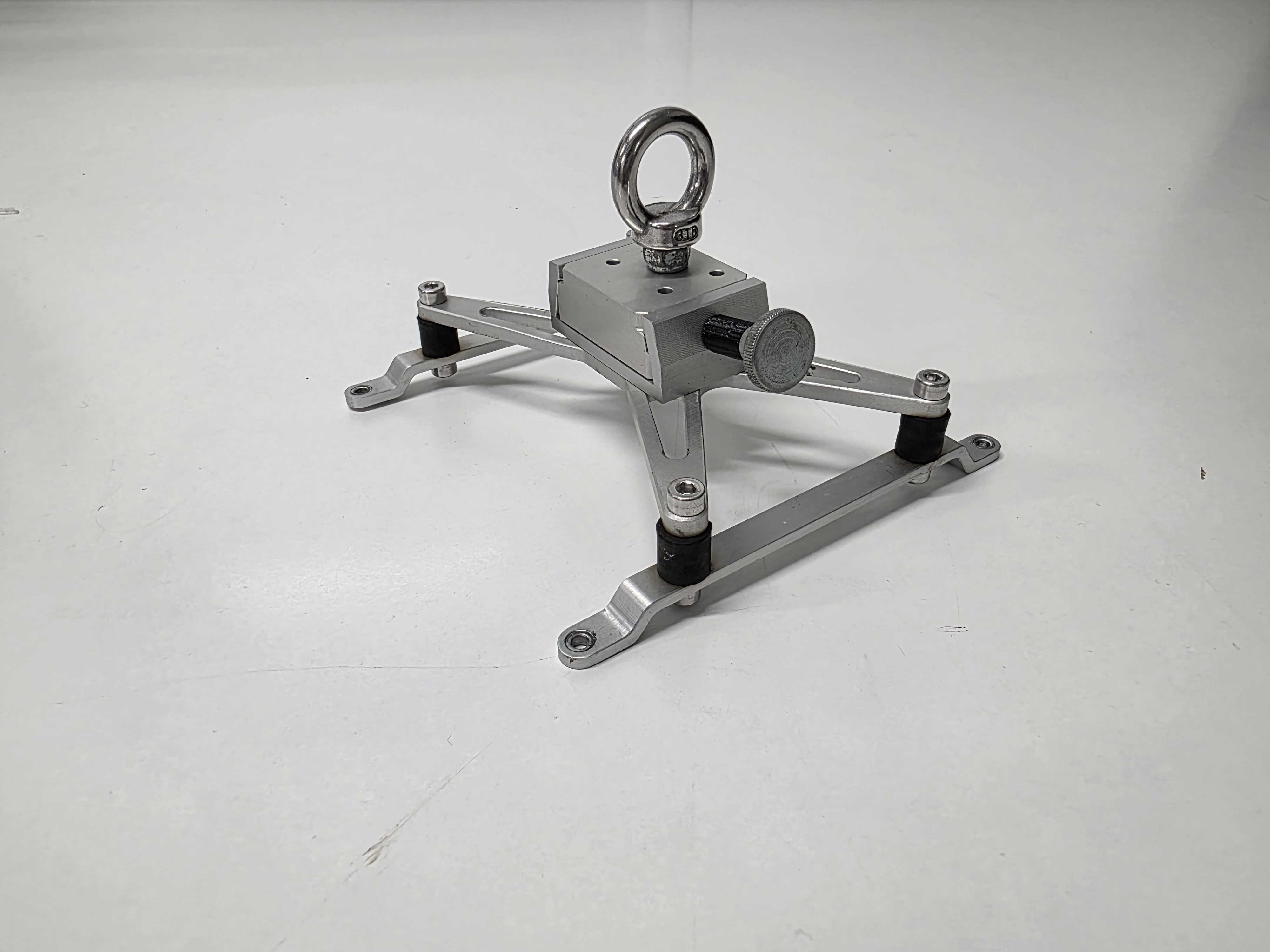 |
| DJI M400 | Old heavy mount | 31 | 17,5 | 15,5 | 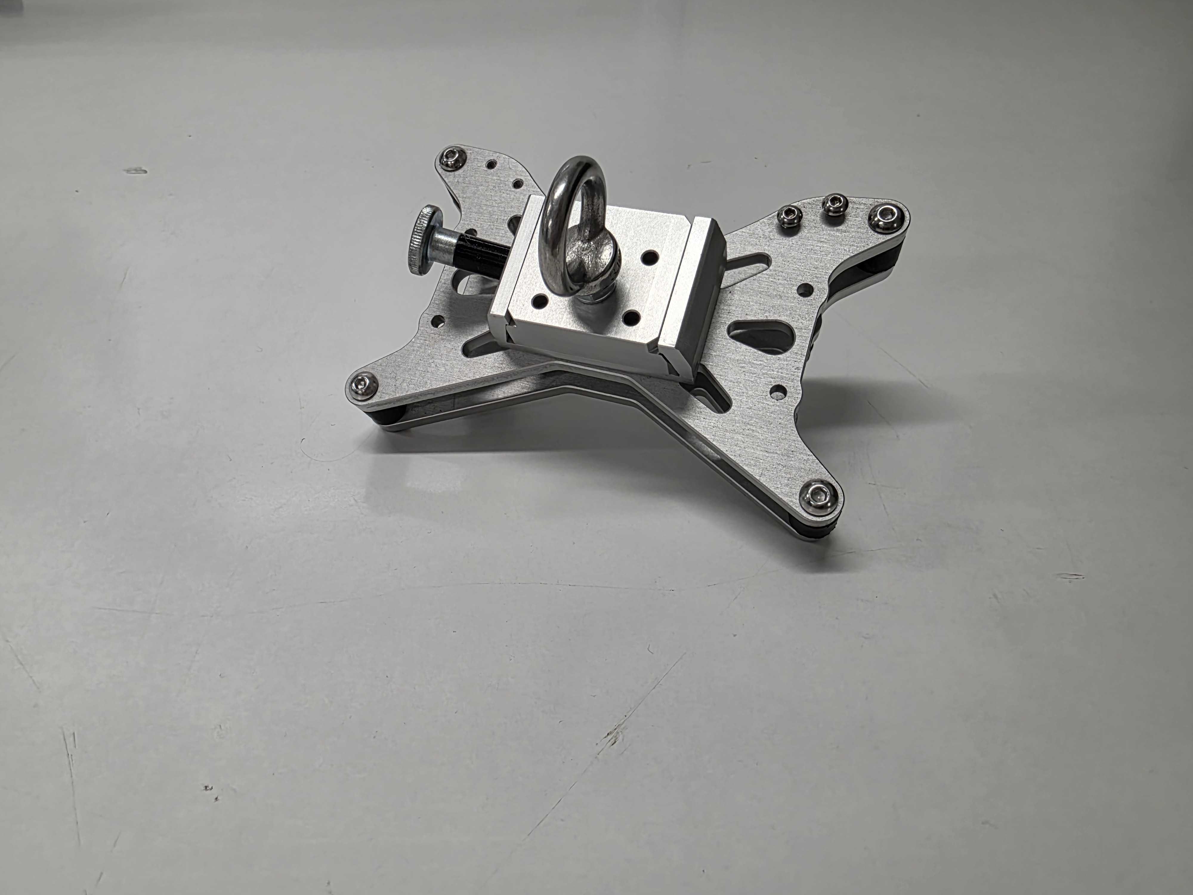 |
| DJI M400 | New heavy mount | 31 | 16 | 16 | 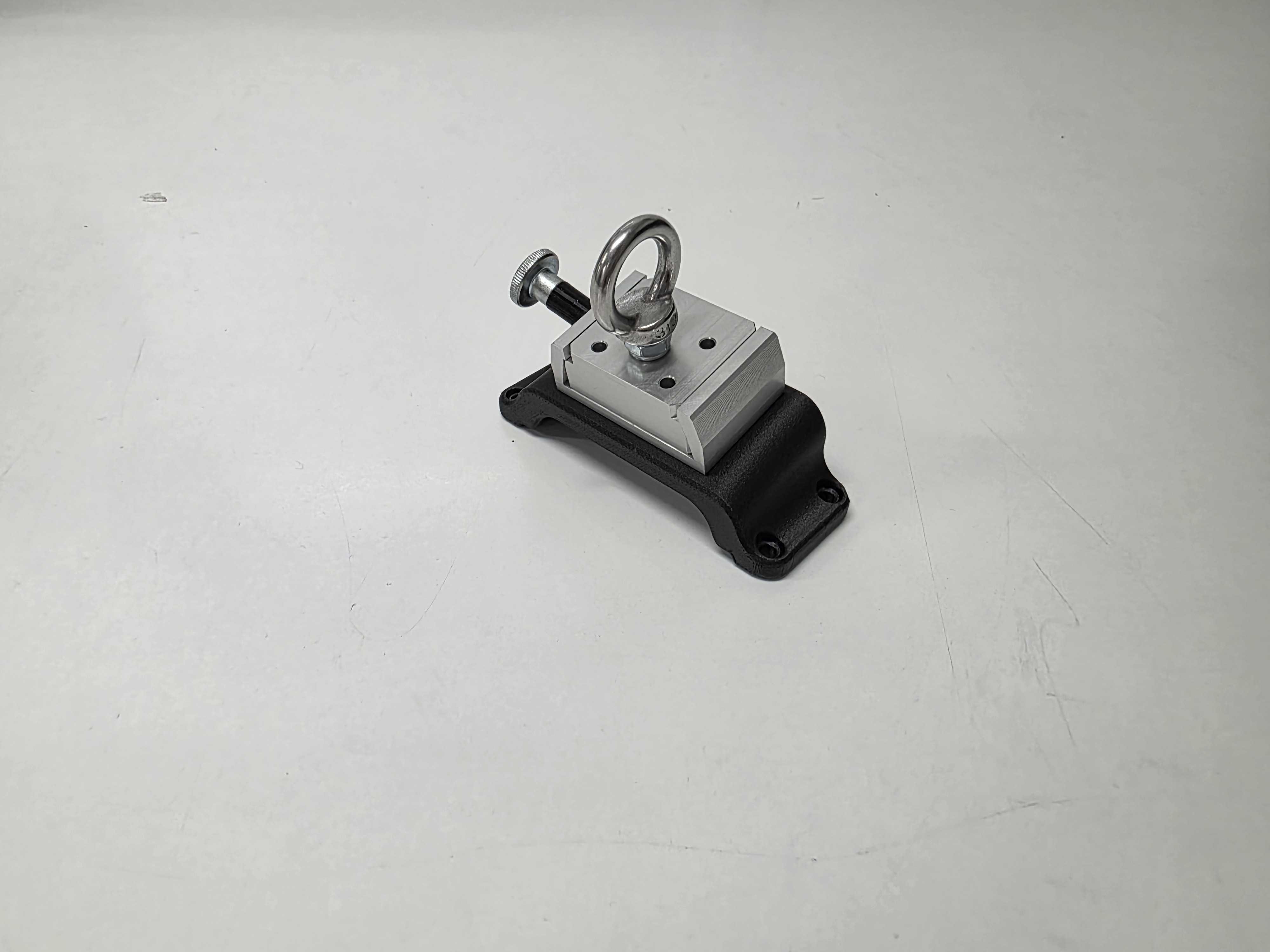 |
| DJI M400 | Manifold heavy mount | 31 | 13,8 | 13,8 | 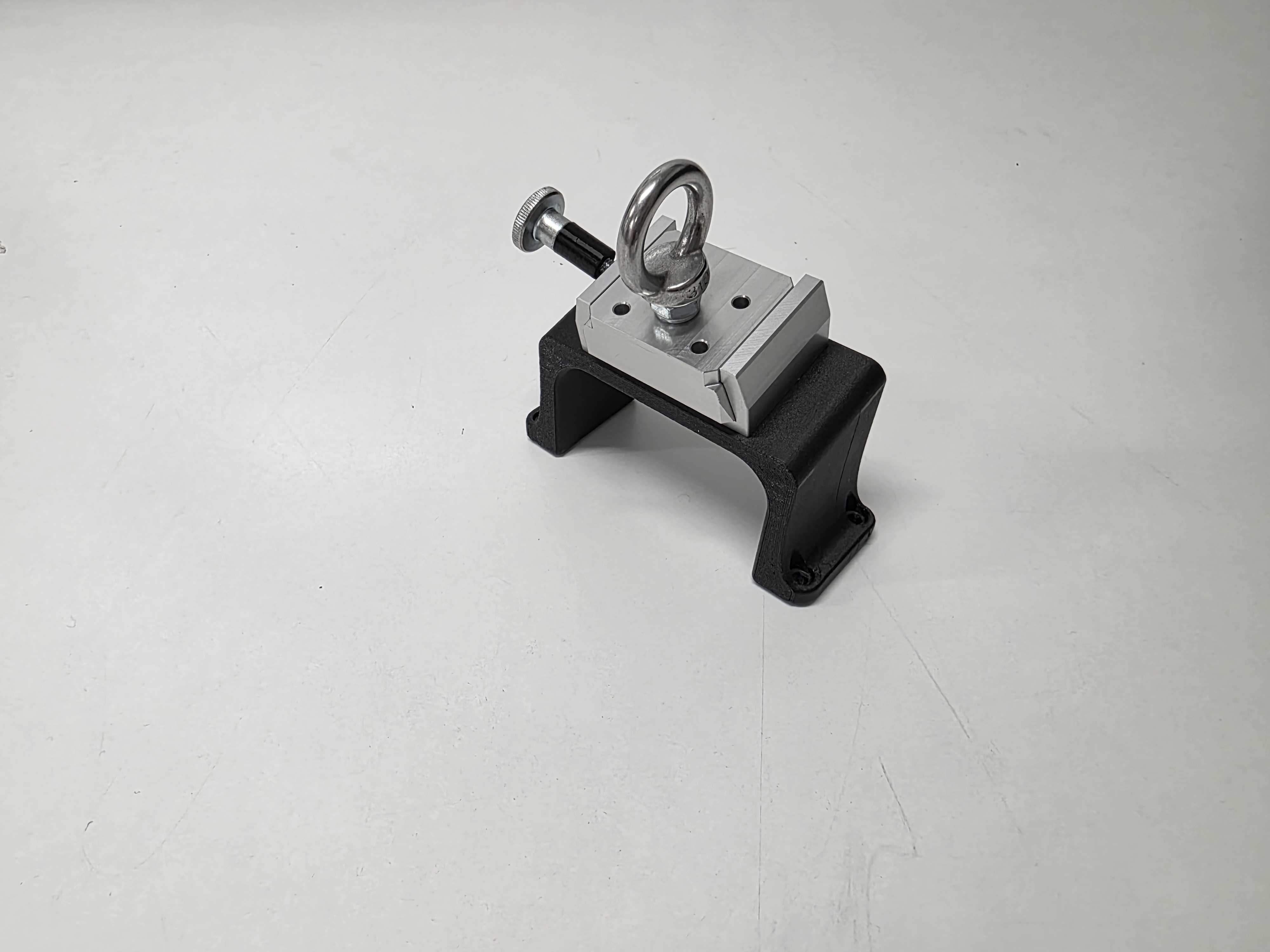 |